Help Desk
Why do I have Carryover?
Sep 03 2013
Author: Chromatography Today Help Desk on behalf of Chromatography Today Help Desk
Within the field of quantification one of the biggest limitations of an analytical procedure is the dynamic range of the assay. Some of the challenges associated with this statement will be addressed and approaches investigated which can be utilised to reduce the amount of memory effect within an analytical system which can dramatically limit the dynamic range and precision of the assay.
Memory effects or carryover can have consequential effects in many areas where separation science is used, from the world of bioanalysis to that of forensics to that of environmental studies [1-3]. The issue that arises is that unless the entire sample is removed from the analytical system the subsequent analysis will have residual compound from the previous injection which could potentially lead to inaccurate data being produced. So what steps can be taken to alleviate this issue? There are several approaches which can be employed to mitigate the risk; one approach is to ensure that samples that are known to have high concentrations are never analysed directly before samples which are known to have very low concentrations. Another approach is to add extra blank samples to reduce the amount of carryover seen by the real samples. Yet another approach is to dilute samples into a limited calibration range.
All of these approaches are used routinely in many laboratories; however these solutions in themselves are not ideal, as it will lead to longer analysis times and greater sample manipulation. Ideally it would be much better to address the issue of carryover within the method development stages of the chromatographic development to ensure that the levels of carryover are kept to a minimal amount.
So how does an analyst go about reducing the levels of carryover from their chromatographic system? One approach that has been applied successfully to this issue is to ‘Isolate and Eliminate’ [4]. This is a process that has to be done systematically by sequentially removing components from the chromatographic system to determine where the source of the carryover is. The second stage is then to determine what needs to happen to remove it from the system. This could be physically replacing a faulty or contaminated component or by altering a wash solvent or mobile phase.
Isolation
There are several components which can act as a source of carryover, and the first stage is to determine the source of this carryover, and to also determine the nature of the carryover. The carryover can be coming from;
• Contaminated blank sample
• Contaminated mobile phases (noticeable on gradient separations)
• Autosampler
• Column
• Detector
To determine if carryover is coming from a particular component it is necessary to do a series of high concentration followed by removing from the system the suspect component and then blank sample injections to determine if the hypothesis was correct or not.
In terms of the nature of the carryover there are two main states:
• it can be removed with a very few blank injections
• it is persistent and does not seem to decay appreciably with repeat injections
The former is preferable since there is a suggestion that the approach to removing the compound is working, whereas the latter findings suggests that there is an inherent problem with the chromatographic system, probably contamination.
If there is contamination suspected then this is relatively trivial to resolve, although there have been examples where it is a buffer that has been contaminated and this may not be so obvious as to why this is causing an issue. Thus, if contamination is suspected then it is important that all potential sources of contamination are removed to ensure that the issue is addressed.
If the carryover is not from a contamination source then further isolation of the chromatographic system has to be performed. The first component to isolate is the autosampler valve. The injection of a high standard with the chromatographic system set up in its original state followed by a “blank” injection with the autosampler removed from the chromatographic system will determine if the carryover is coming from the autosampler or from the rest of the system. There are currently many different autosamplers on the market, however they all work in a similar manner. Central to the design is the use of a two position port valve, which is used to transfer the sample from an injection device to the fluidic system of the chromatography system.
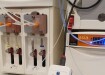
For simplicity, an autosampler which uses a syringe to draw up the sample and then inject this sample into a sample loop will be discussed; however the principles of the approach can be readily applied to any type of autosampler. In this type of system the sample is drawn directly into the barrel of a syringe and then the sample is injected onto the chromatographic system using a 2 position valve, connected with a sample loop. Other systems may use a piece of inert tubing between a syringe or metering device and the sample, but the basic concepts are very similar. Investigating the components that the sample comes into contact with (Figure 1), it can be seen that there are several locations where the sample can be effectively trapped.
The Syringe
There is a substantial opportunity for the sample to be trapped/adsorbed on the glass surface of the syringe or the metallic surface of the needle. If the seal between the plunger and the glass syringe barrel is not tight enough then there is a possibility of either;
• air being drawn in as the plunger is filling the syringe, reducing the amount of sample present in the syringe
• when the plunger is being pushed down there is a possibility that the sample will leak through the plunger seal and the glass barrel, resulting in sample being deposited in the barrel and /or plunger. In terms of carryover this can be very significant.
The Injector Valve
This relates to the swept volume as the sample goes from the syringe to the injector loop. Within the valve there are regions which are not properly swept due to the fluid dynamics of the arrangement, highlighted in Figure 2. This will result in a possibility of sample being retained within the rotor or on the stator. As the rotor rotates between the load and the inject position so the sample will come into contact with the stator and this will result in a possibility that the sample will be retained on the stator. Defects in the surface of the rotor or stator, such as scratches or small abrasions can be a major cause for carryover in this scenario. If there are solubility issues in transferring the sample into the sample loop then it is possible that small deposits of the analyte will remain on the individual valve components.
Carryover on the column
There are other components where the sample can be irreversibly retained and there are a range of reasons why this should occur. The column will typically have a very large surface area and so the possibility of some of the sample not being eluted from the column can be quite high. It is therefore possible that not all of the sample will be removed from the column after it is injected. This can occur if the analyte has a limited solubility range in the mobile phase, prevalent with proteins and other macromolecules. If this is the case then that component will be available for elution on the next injection which will result in an incorrect determination of the analyte concentration. Different columns will have different degrees of retentivity [5] which is further complicated by the inclusion of columns where matrix has been injected which will change the retention mechanism for the sample and potentially cause the creation of highly retentive sites which do not preferentially elute the compounds of interest.
Initially it is important to determine the nature of the carryover; is it at a persistent level or does it disappear after a few washes? This is a relatively easy test to perform, simply inject a high concentration followed by a series of blanks from the same vial. Obviously this raises the question that the blank could be contaminated. This can be tested using a variety of different sources of a blank and repeating the previous test. If the levels of analyte response do not drop then a source of possible contamination should be investigated.
To determine where the carryover is located there are a series of experiments that need to be performed.
It is one thing to isolate the carryover; however it is also necessary to have an approach to remove the carryover. If the carryover is coming from the column, then a change in the mobile phase, increasing the amount of strong solvent, altering the pH, altering the flow rate will have an effect on the solubility of the analyte and hence the levels of carryover. Also, it is worthwhile checking that the column has been installed correctly.
If the carryover is not coming from the column then further investigations can be made to reduce the chromatographic system further to isolate fewer and fewer components. Reassembling the autosampler, the next easiest component to remove is the syringe. Again the system is set up so that it is in a normal operating mode and then a high standard is injected, following this the syringe is removed or disabled so that it is not possible for sample to be introduced from the syringe. Thus carryover can only come from the valve, assuming that the column carryover has been checked. If the carryover is negligible then the carryover is coming from the one component that has been removed, which in this case is the syringe.
If the carryover is coming from the syringe then the syringe should be checked to make sure that there is a tight fit between the barrel and the plunger. There should also be a visual inspection of the syringe to ensure that there are no obvious aberrations in the walls of the barrel, on the plunger or in the needle tip.
In a similar fashion if the carryover is coming from the valve it is worth checking to see if there is any wear and tear on the stator or the rotor. In most cases these are easily accessible and can be viewed with some ease.
In both situations if there is no obvious physical manifestation then the choice of wash solvent and the volume of wash solvent becomes critical [6]. It is important that the wash solvent is chosen to ensure that there is maximum solubility of the compound obtained [7]. For organic compounds the work of Snyder [8] to categorise different solvents may be used and then wash solvents may be employed that utilise the appropriate solvent to optimise the solvation of the compound thus reducing the carryover. If the physiochemical properties of the molecule are not understood then using a mixture of solvents that cover a range of solvent properties is a more generic approach that will give some success. The choice of pH can also be important as for ionisable compounds this will result in the compound being in a charged or uncharged state which will increase or reduce the solubility of the compound [9].
Example 1
An example where carryover was observed on the column is given in Figure 3, and was given by Joe from Franklin, USA. In this example a basic compound was being analysed using a low pH solvent mixture. The stationary phase was not well end capped and as a result there was quite a considerable amount of secondary interactions which resulted in some tailing but also substantial amounts of carryover. Thus, the top standard with the subsequent blank overlaid is shown in Figure 3a. The levels of carryover observed were nearly 10%, which made quantification virtually impossible. The original blank overlaid with another blank after the autosampler has been removed from the chromatographic system is shown in Figure 3b. This clearly demonstrates that the carryover was not coming from the autosampler and other components need to be investigated instead. It was eventually determined that the carryover was in fact coming from the column. In this example Joe looked at altering the pH of the mobile phase above the pKa of the analyte. This meant that there was no possibility of obtaining an ion exchange interaction and thus virtually eliminating the carryover, Figure 3c.
Example 2
Another example comes from Eilidh, from Runcorn, UK. Eilidh was looking to analyse a series of acetylcholinesterase inhibitors, in particular; edrophonium, neostigmine and pyridostigmine. Eilidh was looking a large dynamic range covering 0.1 ng/mL through to 100 ng/mL from a 200μL sample of plasma extracted on a WCX material and then analysed using HILIC. The high levels of organic solvent associated with HILIC in general mean that there is less carryover. However in this case Eilidh was finding that the levels of carryover were not acceptable following the high standard compared to the response obtained from the low standard (Figure 4a, b). Employing the approach of isolate and then eliminate it was determined that the carryover was actually coming from the autosampler valve. On inspection of the rotor and stator it became obvious that the issue was associated with a contaminated valve. Cleaning the stator in a solution of acidic methanol in a sonic bath and also replacing the rotor reduced the levels of carryover dramatically, as seen in Figure 4c, which allowed the dynamic range of the assay to be extended. Care does have to be taken with this approach to ensure that more active adsorptive sites are not produced, as this will increase carryover levels.
Example 3
The next example we have is from Joanne from Cheshire, UK. Joanne was looking at developing a HILIC method, and as part of the method development process observed some very large levels of carryover. It very nicely demonstrates the importance of wash solvents on the chromatographic system. In this scenario performing the tests that have been previously outlined it was evident that the carryover was coming from the autosampler and in particular was highlighted to be due to the wash solvents. In Figure 5a, is a blank injected directly after the top standard with the wash solvent which was left on the system from a reversed phased system (IPA, MeCN, Acetone 45:45:10). Figure 5b demonstrates the importance of the wash solvents can have on the levels of carryover. In this situation the wash solvent was altered to water which is a much more appropriate solvent for very polar molecules, as there are less solubility issues. As Joanne observed in this scenario the choice of the wash solvent was critical.
However this also raises another important fact, which is that there is no universal solvent to remove carryover, it really does depend on the molecule that is being investigated. Use of pH [9] and the Snyder triangle [8] can aid in the choice of a more applicable solvent, but in all cases where carryover is present the nature and the source of the carryover have to be considered in conjunction with the nature of the compound. The Synder triangle classifies solvents according to three parameters and this will allow the correct solvent to be chosen which best matches the physiochemical properties of the analyte to ensure minimal carryover.
Conclusion
Carryover is a major challenge for separation scientists in many industries often resulting in a compromise in the quality of data being produced or increasing assay complexity. This may be addressed using the approach highlighted in Figure 7, which has been successfully employed to initially isolate the carryover and then eliminate it by replacing contaminated or damaged components or by altering the solvents used to clean individual components. Selection of the correct wash solvent, and sample solvent is an important factor, and this choice must be made in conjunction with the physiochemical properties of the analytes being investigated to optimise the cleaning regime.
References
1. Y. Asakawa, C. Ozawa, K. Osada, S. Kaneko, N. Asakawa, J. Pharm. Biomed. Anal., 43 (2007) 683-690
2. D.A. Armbruster, D.B. Alexander, Clinica Chimica Acta, 373 (2007) 37-43
3. M.C. Hurtado-Sánchez, R. Romero-González, M.I. Rodríguez-Cáceres, I. Durán-Merás, A. Garrido Frenich, J. Chrom. A. in press
4. A. Clouser-Roce, K. Johnson, D. Fast, D. Tang, J. Pharm. Biomed. Anal.47 (2008) 146-155
5. N. Tanake, K. Kimata, K. Hosoya, H. Miyanishi, T. Araki, J. Chrom. A., 656 (1993) 265-287
6. P.T. Vallano, S.B. Shugarts, E.J. Woolf, B.K. Matuszewski, J. Pharm. Biomed. Anal. 36 (2005) 10073-10078
7. S. Dolman, S. Eeltink, A. Vaast, M. Pelzing, J. Chrom. B. 912 (2013) 56-63
8. L.R. Snyder, J. Chrom. A., 92 (1974) 223-230
9. E. Shoghi, E. Fuguet, E. Bosch, C. Ràfols. Eur. J. Pharm. Sci. 48 (2013) 291-300
Digital Edition
Chromatography Today - Buyers' Guide 2022
October 2023
In This Edition Modern & Practical Applications - Accelerating ADC Development with Mass Spectrometry - Implementing High-Resolution Ion Mobility into Peptide Mapping Workflows Chromatogr...
View all digital editions


Events
Apr 23 2024 Kintex, South Korea
Apr 23 2024 Seoul, South Korea
Apr 28 2024 Montreal, Quebec, Canada
May 05 2024 Seville, Spain
May 15 2024 Birmingham, UK